Read many posts to have the pin diagrams for the Kess v2 ecu tuning master Subaru cable. And luckily, i found this:
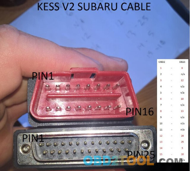
The man has a genuine kess subaru cable., and measured the cable for someone in need.
But it seems there is something wrong.
He has the red obd connector the wrong way round
A mate in the forum also says
”what you have as pin 1 is actually pin 9 and what you have as pin 15 or should be 16 is actually pin 1
when you hold it the other way round you will see pins 4 and 5 are sticking out more than the others, these 2 pins are gnd”
Probably right. The man made up the pin numbers on the OBD connector as reference to the way he did hold the connectors in the picture.
He must have missed pin16 but that pin has no connection to the DB25 so it should not matter.
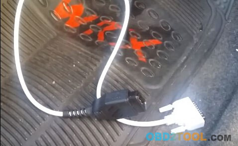
Followed the instruction, i made one and tested ok.
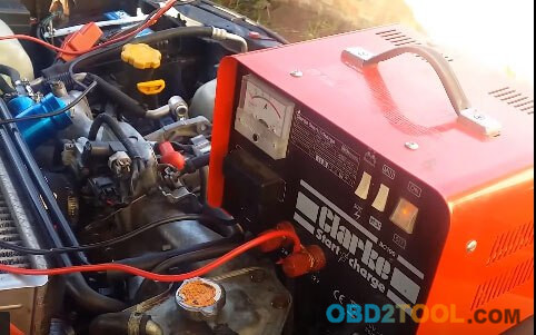
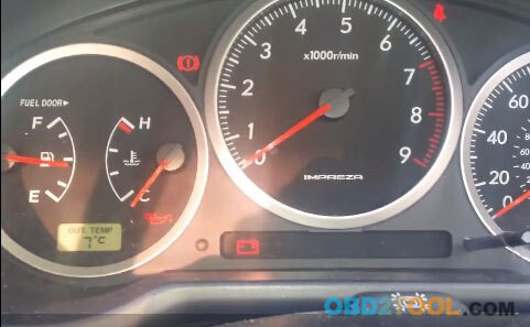
Connect to the battery charger
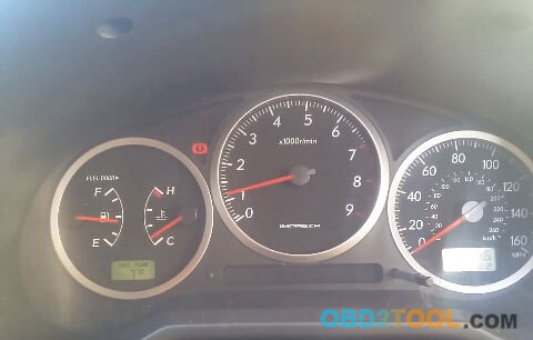
Connect jumpers under the steering wheel
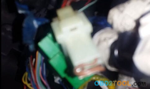
The car now is in service mode
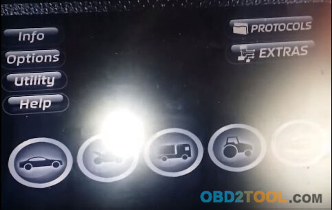
Start Auto ECU Programmer Kess V2 v5.017, and select Car
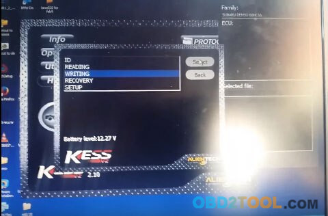
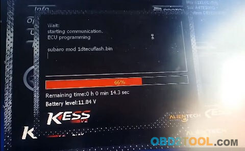
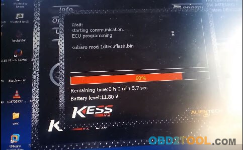
All done
I used it to write ECU successfully.
Ps. Something good i found when i searched info.
Maybe it would helps someone.
According to the OBD generic standard, pins 4 and 5 are designated grounds. But in the 2000-2004 wiring diagrams, pins 12 and 13 are shown as connected to ground. (According to OBDII, pins 12 and 13 are data connections.)
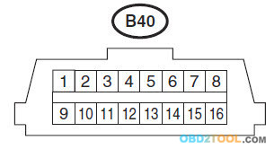
Here’s what the OBDII pin out is supposed to be:
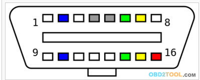
Note that pins 1 to 8 are at the wider side of the connector, and 9 – 16 on the narrower side.
Here’s what Subaru shows in the 2007 (also 2005-9) wiring diagrams:
As we can see, the pin locations are the same as the OBDII standard.
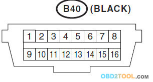
And finally, here’s the way it’s shown in the pre-2005 Subaru wiring diagrams:
Note that the locations of pins 1 to 8 are on the narrower side of the connector, even though the OBDII layout has remained unchanged.
This isn’t just a question of which way the connector is viewed. Pins 1 to 8 are always on the wider side of the connector, whereas the pre-2005 diagrams have them on the narrower side.
This anomaly affects where the connections are made. As noted, in the 2005+ wiring diagrams, pin 16 is shown to be connected to the always-on 12 V. But in the pre-2005 diagrams, pin #1 goes to an always-on source, SBF-5, in the engine compartment fuse box. (There isn’t a separate fuse for the OBD connector 12 V supply.)
In addition, as noted, the apparent inversion of pin locations affects the grounds and data line identification.
So a “heads up” if you’re using 2000-2004 wiring diagrams and working with the connections to the OBD2 scan tool.