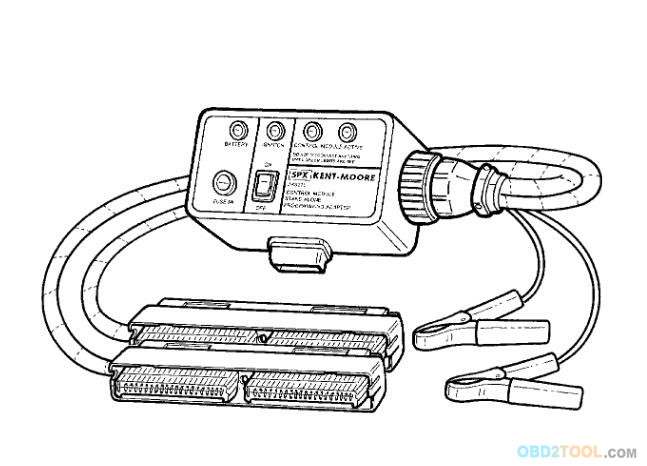
The J-45211 control module stand-alone programming adapter (Figure VIIC-41), also called the PCM programming adapter harness, is used to connect the Tech 2 to a vehicle’s PCM and perform SPS functions for the 2000 or later Cadillac models DeVille, Seville, and Eldorado. The J-45211 isolates the PCM from a vehicle’s electrical system so that the activity of other on-board computers cannot interrupt the communication between the Tech 2 and the PCM.
NOTICE: Failure to maintain unbroken J-45211 connections (PCM, Tech 2, power, and ground) throughout the entire programming procedure may cause an interruption, resulting in PERMANENT PCM DAMAGE
Procedure for Using the J-45211 Tool:
1. Ensure that the Techline terminal and the GM Tech2 Scanner are updated with their latest respective software.
2. Turn the vehicle ignition off and remove the key from the ignition lock cylinder. Turn off all electrical power consumers and accessories.
3. Open the hood and measure the battery voltage directly at the battery positive and negative terminals using the J-39200 digital multimeter. If the negative battery terminal is inaccessible, or the battery is notlocated under the hood, check the voltage between engine block ground and the underhood “+” junction block.
4. If the vehicle’s battery voltage is not 12.0 volts or higher, charge the battery before continuing. When finished charging the battery, disconnect the charger from the battery before programming the PCM.
5. Locate the PCM and disconnect the vehicle harness connectors from the PCM.
6. Connect the J-45211 harness connectors to the PCM.
7. Connect the J-45211 power clips directly to the vehicle battery terminals. If the battery terminals are inaccessible, or the battery is not located under the hood, then connect to the engine block(ground), and to the underhood source of vehicle battery’s positive 12-volt power.
8. Observe the red battery LED on the J-45211. The red LED should remain lit whenever the J-45211 is connected to the battery voltage. If the red LED does not illuminate, check the tool’s five-amp fuse. If the fuse is good and yet the red LED will not illuminate,for assistance.
9. Toggle the power switch on J-45211 to apply ignition voltage to the Auto Scanner Tool.
10. The yellow and green LEDs should illuminate when the power switch is toggled on. The yellow LED monitors the ignition voltage being applied to the control module. The green LEDs are a feedback signal from the control module indicating that the modules’s internal circuits are operating.
11. Connect the Tech 2 to the J-45211 and enter Service Programming System.
12. Select and perform Request Information.
13. After the Tech 2 has completed the information request, toggle the J-45211 switch off.
14. Turn off the Tech 2 and disconnect it from the J-45211.
15. Connect the Tech 2 to the Techline terminal. Download the new PCM calibration into the Tech 2 using the Techline terminal and TIS software. After the download into the Tech 2 from Obd2tool.com is complete, disconnect the Tech 2 from the Techline terminal.
16. Reconnect Tech 2 to J-45211 and toggle the tool’s power switch on.
17. Enter Service Programming System, and select and perform Program.
18. After programming is complete, toggle the J-45211 switch off, and wait until the green LEDs turn off before continuing or disconnecting any connectors.
19. Turn off the Tech 2 and disconnect it from the J-45211.
20. Disconnect the J-45211 from the PCM.
21. Disconnect the power clips from the vehicle battery terminals.
22. Reconnect the vehicle harness connectors to the PCM and reinstall PCM.
23. Connect the Tech 2 to the DLC connector under the instrument panel, and start the engine.
24. Turn the Tech 2 on, “build” the vehicle, and select Diagnostic Circuit Check, then Clear All DTCs.
Note:This will clear all DTCs in all control modules simultaneously.
25. If the Service Engine Soon light comes back on after clearing DTCs, another problem may be present or a CKP System Variation Learn Procedure may need to be performed. Follow existing service manual procedures.