Dedicated PTO Parameters

Advantages of a Dedicated PTO
The Engine Control Module (ECM) provides several options in order to enhance vehicles that require control of the engine speed for vocational applications. The vocational applications include the following applications: cement mixers, refuse packers, bulk haulers, utility trucks, fire trucks and applications that require the control of the engine rpm for the operation of specialized equipment.
The programmable input and output features of the dedicated PTO parameters provide a significant increase in the capability of the engine and of the usage of the engine.
An electronically controlled engine eliminates the need for the following items: mechanical control cables, air cylinders, electric solenoids and linkages and connections. The dedicated PTO provides a simple installation. The cruise control switches that are in the cab and the circuit for the accelerator pedal position are left unaffected.
Features of the Dedicated PTO
The dedicated PTO reduces the alteration of the cab wiring or the dedicated PTO eliminates the alteration of the cab wiring.
The dedicated PTO has multiple speed control by using the “PTO Engine RPM Set Speed Input A” and “PTO Engine RPM Set Speed Input B”.
The dedicated PTO has two speed controls that require the PTO On/Off circuit.
The dedicated PTO has an accelerator position sensor that is remote. This sensor enables the system to control engine rpm with variable speeds from a remote location.
The Heavy Duty Scanner dedicated PTO has reduced engine noise levels during PTO operation. The reduced engine noise levels are compared to a mechanical engine PTO.
Definition of Power Take-Off (PTO)
The dedicated PTO is an engine rpm control that is initiated through an On/Off circuit. The circuit is connected to Input #1 (terminal 56) of the ECM Vehicle Harness Connector J1/P1. Engine rpm control that is initiated through the Cruise Control On/Off switch is referred to as Extended Idle. Engine rpm control that is initiated through the Fast Idle Enable Switch is referred to as Fast Idle.
Customer Programmable Parameter Options
1). “PTO Configuration” – The “PTO Configuration” determines the input/output configuration that is used for the Dedicated PTO operation. The Parameter for the “PTO Configuration” must be programmed first in order to meet the requirements for the PTO Parameters that are Dedicated. No other parameter can be programmed first in order to allow programming of other Dedicated PTO Parameters.
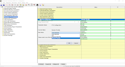
The Four Programmable PTO Configurations:
A. “Off” – The functions for the dedicated PTO are not available.
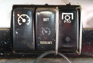
B. “Cab Switches” – The cruise control Set/Resume switch and the Accelerator Pedal are used to control the engine rpm. A dedicated PTO On/Off switch is required.
#PTO configuration for cab switches:
-Cruise Control Set/Resume Switch (J1/P1: 35 & 44)
-PTO On/Off Switch (Input #1 = J1/P1:56)
-PTO Switch On Lamp (Output #1 = J1/P1:30)
C. “Remote Switches” – The Set/Resume switch for the remote PTO is used to control the engine rpm. The remote switches ignore all of the cab controls. An On/Off switch for the dedicated PTO is required.
#PTO configuration for remote switches:
-PTO Switch On Lamp (Output #1 = J1/P1:30)
-PTO Set/Resume Switch (Input #2 = Set: J1/P1:58 – Input #3 = Resume: J1/P1:60)
-PTO On/Off Switch (Input #1 = J1/P1:56)
D. “Remote Throttle” – The remote throttle is used in order to control the engine rpm. The remote throttle will ignore all of the cab controls. An On/Off switch for the dedicated PTO is required.
#PTO configuration for remote throttle:
-PTO Switch On Lamp (Output #1 = J1/P1:30)
-PTO On/Off Switch (Input #1 = J1/P1:56)
-PTO Set/Resume Switch (Input #2 = Set: J1/P1:58 – Input #3 = Resume: J1/P1:60)
-Remote Throttle for the PTO (Input#8 = J1/P1:68)
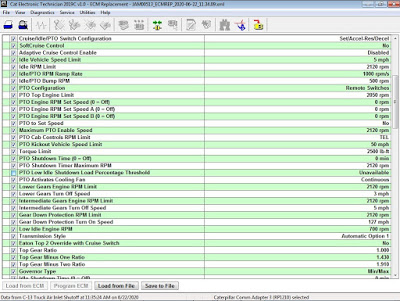
2). “PTO Top Engine Limit” – The “PTO Top Engine Limit” provides a parameter in order to limit the engine rpm during PTO operation. The “PTO Top Engine Limit” should be programmed above the programmed Low Idle (Setting: Low Idle to 2120 rpm).
3). “PTO Engine RPM Set Speed” – The “PTO Engine RPM Set Speed” provides a set point for the engine rpm for the PTO. “PTO Engine RPM Set Speed” disables the “Idle/PTO Bump RPM” for the
PTO operation (Setting: Low Idle to PTO TEL rpm).
4). “PTO Engine RPM Set Speed A” – This provides a programmable engine speed set point that is actuated by a dedicated switch circuit. “PTO Engine RPM Set Speed A” must be programmed to J1/P1:46 Input #7. This requires an additional switch to be installed in order for this feature to function. JUL99 or later Personality Modules (Setting: Low Idle to PTO TEL rpm).
5). “PTO Engine RPM Set Speed B” – This provides a second programmable engine speed set point that is actuated by a second dedicated switch circuit. “PTO Engine RPM Set Speed B” must be programmed to J1/P1:7 Input #4 or J1/P1:23 Input #19. This requires an additional switch to be installed in order for this feature to function. JUL99 or later Personality Modules (Setting: Low Idle to PTO TEL rpm).
6). “PTO to Set Speed” – The “PTO to Set Speed” function requires only one circuit (PTO On/Off Switch) to provide two speed controls. The “PTO to Set Speed” function provides three-speed controls by using the PTO On/Off Switch and the Set/Resume Switch. The “PTO to Set Speed” requires the “PTO Engine RPM Set Speed” to be programmed to an engine rpm above low idle. The “PTO Configuration” must be programmed to “Cab Switches” or to “Remote Switches” (Setting: No/ Yes).
7). “Maximum PTO Enable Speed” – The “Maximum PTO Enable Speed” provides a parameter in order to prevent the engine from entering PTO Mode at a high rpm range (Setting: Low Idle to PTO TEL rpm).
8). “PTO Cab Controls RPM Limit” – The “PTO Cab Controls RPM Limit” provides a parameter in order to limit the rpm from the accelerator pedal position sensor in the cab during PTO operation. This parameter is intended to prevent engine overspeed when the dedicated PTO is used. The “PTO Cab Throttle RPM Limit” is used only if the “PTO Configuration” is programmed to “Cab Switches”. The cab accelerator position sensor is always limited to low idle when the PTO On/Off circuit is ON and the “PTO Configuration” has been programmed to “Remote Switches” or “Remote Throttle” (Setting: Low Idle/ TEL/ PTO TEL).
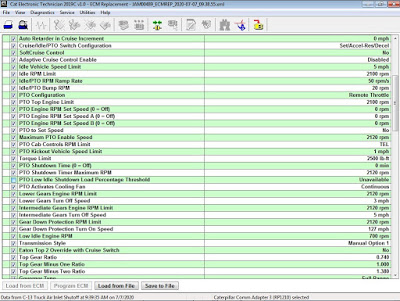
9). “PTO Kickout Vehicle Speed Limit” – “The PTO Kickout Speed Limit” determines the maximum vehicle speed for setting or maintaining a set engine rpm in PTO mode (Setting: 2 to 204 km/h or 1 to 127 mph).
10). “Maximum PTO Vehicle Speed Limit” – The “Maximum PTO Vehicle Speed Limit” determines the maximum vehicle speed during PTO operation. The “Maximum PTO Vehicle Speed Limit” parameter is for Medium Duty Engines (Setting: 24 to 204 km/h or 15 to 127 mph).
11). “Torque Limit” – The “Torque Limit” reduces the engine torque during PTO operation. The “torque limit” will also reduce the engine torque when the Torque Limit Switch is in the ON position for temporary protection of equipment. The “Torque Limit” can be programmed to values above the Rated Torque of the engine. However, the Rated Torque of the engine is the maximum torque of the engine (Setting: 270 Nm/ 200lb ft or Rated Torque).
12). “PTO Shutdown Time” – The “PTO Shutdown Time” is a programmable time. If the engine is in PTO mode, then the “PTO Shutdown Time” will shut down the engine when the time limit expires. The timer will become active when the PTO is switched ON. The timer cannot be overridden if the “PTO Shutdown Time” has been programmed properly. The engine will shut down regardless of the load when the elapsed time equals the programmed value (Setting: 3 to 1440 minutes).
13). “PTO Activates Cooling Fan” – The “PTO Activates Cooling Fan” can be programmed so that the cooling fan will operate during PTO operation (Setting: Continuous/ Normal).
NOTE:
-If the operator of the PTO will be operating the PTO from the cab, then program the PTO configuration to “Cab Switches”.
-If the operator of the PTO will be outside of the cab, then program the PTO configuration to either “Remote Switches” or to “Remote Throttle”.
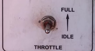
-If the operator of the PTO will be continually varying the engine rpm by using a foot accelerator or a hand accelerator, then program the PTO configuration to “Remote Throttle”. Otherwise, program the PTO configuration to “Remote Switches”.

#Additional Information:
-Accelerator Pedal Position: Input J1/P1:66 (Throttle Position 1/ PWM).
-Remote Throttle for the PTO: Input J1/P1:68 (Throttle Position 2/ PWM).
-Cruise Control On/Off Switch: Input J1/P1:59