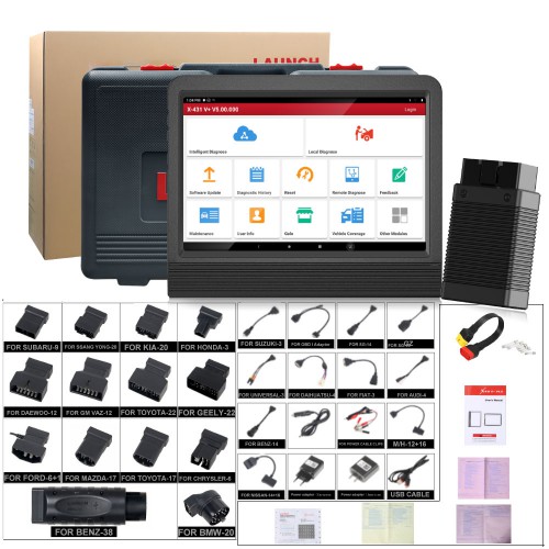
Launch X431 V+ Pro3 Auto diagnostic scanner Wifi 10.1inch Tablet Plus X431 HD3 Heavy Duty Module Supports Both Cars and Trucks for diagnostics. It is 2 years free update online, and X431 HD3 Heavy Duty Module is with one year free update. They can still work well without update.

This article aims to tell the customers “How to Prepare Your Launch X431 V+ PRO3 to Be Ready For Vehicle Test”. Check specific content below.
We should first know the “Diagnostics toolbar” of this tool:
The diagnostics toolbar contains a number of buttons that allow you to print the displayed data or make other controls. It is displayed on the upper right corner of the screen and goes through the whole diagnostic session. The table below provides a brief description for the operations of the diagnostics toolbar buttons:
| Name | Button | Description |
| Home | Returns to Job menu screen. | |
| Tap to print the current screen. To performprinting, you need to purchase an extra Wi-Fi
printer manufactured by LAUNCH separately and then properly configure the wireless printer |
||
| Exit | To exit the diagnostic application. |
After that, we should also know how to do the “Connections” in this tool.
Supposing it is under Normal testing conditions:
* Turn on the vehicle power supply.
* Vehicle battery voltage range should be 9-18V.
* Throttle should be closed at its close position.
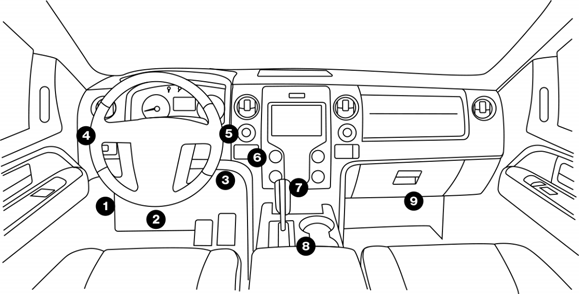
Get to know the DLC location:
The DLC (Data Link Connector or Diagnostic Link Connector) is typically a standard 16-pin connector where diagnostic code readers interface with the vehicle’s on-board computer. The DLC is usually located 12 inches from the center of the instrument panel (dash), under or around the driver’s side for most vehicles. If DLC is not located under dashboard, a label should be there telling location. For some Asian and European vehicles, the DLC is located behind the ashtray and the ashtray must be removed to access the connector. If the DLC cannot be found, refer to the vehicle’s service manual for the location.
Then, (1)the Vehicle connection (For Passenger Vehicle Configuration):
The method used to connect the VCI device to a vehicle’s DLC depends on the vehicle’s configuration as follows:
* A vehicle equipped with an OBD II management system supplies bothcommunication and 12V power through a standardized DLC.
* A vehicle not equipped with an OBD II management system suppliescommunication through a DLC connection, and in some cases supplies 12Vpower through the cigarette lighter receptacle or a connection to the vehicle battery.
Follow the steps mentioned below to connect OBD II vehicle:
* Locate vehicle’s DLC socket.
* Plug the VCI device into the vehicle’s DLC socket (It is suggested to use theOBD II extension cable to connect the VCI device and DLC socket).
* Choose one of the two ways to obtain power from:
* Power adaptor: Connect one end of the included power adaptor tocharging port of the tablet, and the other end to AC outlet.
* Internal battery pack
For non-OBDII vehicle, proceed as follows:
* Locate vehicle’s DLC socket.
* Select the corresponding non-16pin connector.
* Plug the non-16pin end of the connector into the DLC socket, then connecttheother end to the OBD I adaptor, and then tighten the captive screws.
* Connect the other end of the adaptor to the included VCI device.
* If the pin of the DLC is damaged or has insufficient power, please follow theeither of the following methods to proceed:
A.Cigarette Lighter cable (optional): Connect one end of the cigarette lighter cable to vehicle’s cigarette lighter receptacle, and the other end to the power jack of OBD I adaptor.
B.Battery Clamps Cable: Connect one end of the battery clamps cable to vehicle’s battery, and the other end to the power jack of OBD I adaptor.
(2)Vehicle connection (For Commercial Vehicle/Gasoline & Diesel Vehicle Configuration)
The method used to connect the VCI module to a vehicle’s DLC depends on the vehicle’s configuration as follows:
A. OBD II Vehicle Connection: Plug one end of the diagnostic cable into thevehicle’s DLC, and the other end into the diagnostic socket of the VCI module,and then tighten the captive screws.
B. Non-OBD II Vehicle Connection: For vehicles with non-OBD II diagnosticsocket, a non-16pin connector (adaptor cable) is required.
Important message:
a). For commercial vehicles, refer to the above connection method to proceed.
b). For passenger vehicles, replace the “Non-16pin connector” with “OBD I adaptor” +“non-16pin connector (for passenger vehicles)”. Other connections shall also apply.
That’s all. Thank you for sharing your time with us!