Caterpillar Inc. machine air conditioners use pressure switches to protect the air conditioning compressor. To further protect other electrical components in the air conditioning system, arc suppressors are used to discharge inductive loads when the compressor is deactivated. Failure of the arc suppressor can affect the reliability of the pressure switch and cause it to fail. This guide will show you how to test air conditioning electrical components for the Caterpllar 924G wheel loader 3DZ.
All Caterpillar machine service manuals and EPC parts please refer to:2021 CAT SIS EPC+Service Manual Free Download
And for Caterpillar machine diagnostics,please use Cat ET 2022 Diagnostic Software
Procedures:
The following procedures are for testing pressure switches and arc suppresser components attached to the air conditioning system:
Equipment needed:
* 146-4080 Digital Multimeter, or similar digital multimeter with diode testing capability
* Multimeter Probe Kit
Testing Pressure Switches:
114-5333 and 114-5334 High/Low Pressure Switches (NORMALLY OPEN)
In general, the two pressure switches used to protect the air conditioning compressor on Caterpillar machines are part numbers 114-5333, and 114-5334. The only difference in these switches is the connector. Functionally, they are the same. Only one of these is used per machine. These high/low pressure switches have three potential switch positions. These positions are:
1.Open Indicating low system pressure
2.Closed Correct system pressure present
3.Open Indicating high system pressure
Positions 1 and 3 protect the air conditioning system by preventing the compressor from actuating when potentially harmful pressure conditions exist. Position 2 is the normal operating switch position.
The following table details the pressure switch logic of these two switches:
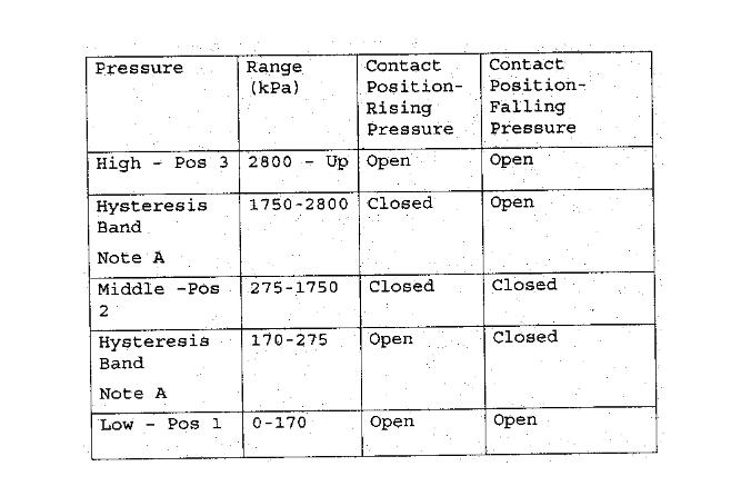
NOTE: Pressure must pass through the hysteresis band to provide correct contact condition.
To test the switch:
1.Disconnect the switch from the machine harness.
2.Connect the 146-4080 Mulimeter to the two connector pins, and place the meter in the Ohms position.
3.Measure the switch resistance.
4.If the system is charged to above 275kPa, and below 1750kPa, the meter will display less than 1 ohm.
5.If the resistance displayed is “OL” (high resistance), and the system pressure is within acceptable limits, replace the switch.
6.Every time the switch fails, also test for arc suppressor functionality.
7.If the switch is removed, ensure the new switch wires are securely cable-wrapped to prevent vibration damage.
NOTE: The meter can display “OL” if the switch contacts are dirty. The switch contacts can become dirty if the arc suppressor is no longer functioning.
NOTE: The meter will display “OL” if the switch is not threaded into the A/C system.
The meter will display “OL” if the switch is not threaded into the A/C system.
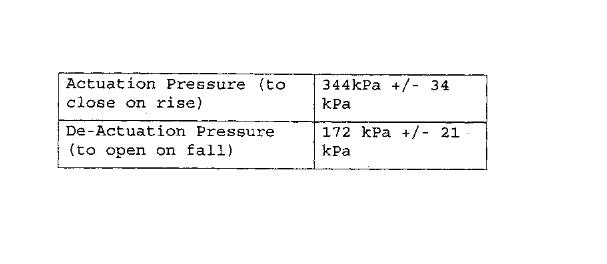
8T-8639 Low Pressure Switch (NORMALLY OPEN)
Switch Specification
To test the switch:
1.Disconnect the switch from the machine harness.
2. Connect the 146-4080 Mulimeter to the two connector pins, and place the meter in the Ohms position.
3. Measure the switch resistance.
4. If the system is charged above 344kPa±34kPa, the meter will display less than 1 ohm.
5. If the resistance displayed is “OL”, and the system pressure is not below specification, replace the switch.
6. Every time the switch fails, also test for arc suppressor functionality.
7. If the switch is removed, ensure the new switch wires are securely cable-wrapped to prevent vibration damage.
NOTE: The meter can display “OL” if the switch contacts are dirty. The switch contacts can become dirty if the arc suppressor is no longer functioning.
NOTE: The meter will display “OL” if the switch is not threaded into the A/C system.
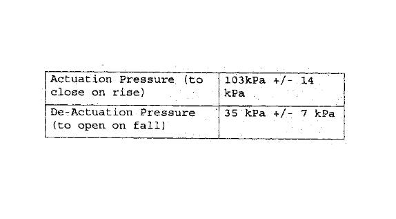
149-6371 Low Pressure Switch (NORMALLY OPEN)
Switch Specification
To test the switch:
1.Disconnect the switch from the machine harness.
2.Connect the 146-4080 Mulimeter to the two connector pins, and place the meter in the Ohms position.
3.Measure the switch resistance.
4.If the system is charged above 103kPa±14kPa, the meter will display less than 1 ohm.
5.If the resistance displayed is “OL”, and the system pressure is not below specification, replace the switch.
6.Every time the switch fails, also test for arc suppressor functionality.
7.If the switch is removed, ensure the new switch wires are securely cable-wrapped to prevent vibration damage.
NOTE: The meter can display “OL” if the switch contacts are dirty. The switch contacts can become dirty if the arc suppressor is no longer functioning.
NOTE: The meter will display “OL” if the switch is not threaded into the A/C system.
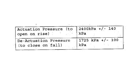
3E-6462 High Pressure Switch (NORMALLY CLOSED)
Switch Specification
To test the switch:
1.Disconnect the switch from the machine harness.
2.Connect the 146-4080 Mulimeter to the two connector pins, and place the meter in the Ohms position.
3.Measure the switch resistance.
4.If the system is charged below 2400kPa±140kPa, the meter will display less than 1 ohm.
5.If the resistance displayed is “OL”, and the system pressure is not above specification, replace the switch
6.Every time the switch fails, also test for arc suppressor functionality.
7.If the switch is removed, ensure the new switch wires are securely cable-wrapped to prevent vibration damage.
NOTE: The meter can display “OL” if the switch contacts are dirty. The switch contacts can become dirty if the arc suppressor is no longer functioning.
NOTE: The meter will display less than 1 ohm if the switch is not threaded into the A/C system.
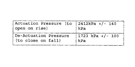
7X-1076 High Pressure Switch (NORMALLY CLOSED)
Switch Specification
To test the switch:
1.Disconnect the switch from the machine harness.
2.Connect the 146-4080 Mulimeter to the two connector pins, and place the meter in the Ohms position.
3.Measure the switch resistance.
4.If the system is charged below 2412kPa±140kPa, the meter will display less than 1 ohm.
5.If the resistance displayed is “OL”, and the system pressure is not above specification, replace the switch.
6.Every time the switch fails, also test for arc suppressor functionality.
7.If the switch is removed, ensure the new switch wires are securely cable-wrapped to prevent vibration damage.
NOTE: The meter can display “OL” if the switch contacts are dirty. The switch contacts can become dirty if the arc suppressor is no longer functioning.
NOTE: The meter will display less than 1 ohm if the switch is not threaded into the A/C system.
Testing Arc Suppressors:
For Part Number 106-8704
1.Place multimeter in diode testing mode.
2.Place red probe in red or plus terminal of multimeter.
3.Place black probe in black or common terminal of multimeter.
4.Place the red probe on Pin 2 of the connector, and place the black probe on Pin 1 of the connector.
5.The multimeter should display between 0.5Vdc and 1.0Vdc.
6.Place the red probe on Pin 1 of the connector, and place the black probe on Pin 2 of the connector.
7.The multimeter should display “OL”.
8.The component is considered failed, and will not provide the required protection, if the above conditions do not exist.9. If the component is failed, replace the component.
For Part Number 3E-9169 and 130-8134
1.Place multimeter in diode testing mode.
2.Place red probe in red or plus terminal of multimeter.
3.Place black probe in black or common terminal of multimeter.
4.Place the red probe on Pin 1 of either connector, and place the black probe on Pin 2 of either connector.
5.The multimeter should display between 0.5Vdc and 1.0Vdc.
6.Place the red probe on Pin 2 of either connector, and place the black probe on Pin 1 of either connector.
7.The multimeter should display “OFL”, or “OL”.
8.Place the red probe on pin 1 of the female connector, and the black probe on the 1 of the male connector.
9.The multimeter should read less than 0.01Vdc. 10. Repeat steps 8 and 9 using pin 2 of each connector.11. The component is considered failed, and will not provide the required protection, if the above stated conditions do not exist.12. If the component is failed, replace the component.
For Part Number 105-8827 and 130-0956
1.Place multimeter in diode testing mode.
2.Place red probe in red or plus terminal of multimeter.
3.Place black probe in black or common terminal of multimeter.
4.Place the red probe on Pin 2 of either connector, and place the black probe on Pin 1 of either connector.
5.The multimeter should display between 0.5Vdc and 1.0Vdc.6. Place the red probe on Pin 1 of either connector, and place the black probe on Pin 2 of either connector.
7.The multimeter should display “OFL”, or “OL”.
8.Place the red probe on pin 1 of the female connector, and the black probe on the 1 of the male connector.
9.The multimeter should read less than 0.01Vdc.10. Repeat steps 8 and 9 using pin 2 of each connector.11. The component is considered failed, and will not provide the required protection, if the above stated conditions do not exist.12. If the component is failed, replace the component.
Correct Mounting of Arc Suppressors:
Certain arc suppressor groups may experience wire lead failure due to vibration if not properly supported.
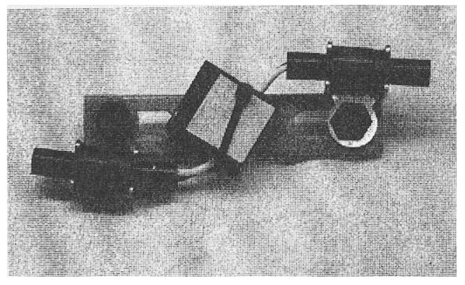
The arc suppressor should be securely cable-wrapped, using a 2U-4497 Strap, to a stationary support to prevent any motion of the suppressor body. Additionally, the connectors on both ends of the suppressor group should likewise be secured.

A suitable bracket for supporting an arc suppressor is the 116-6100 Plate. The addition of a 9R-2926 Plate should permit mounting the 116-6100 Plate around obstacles, if the 116-6100 Plate can not be installed directly in an existing application. The sure seal connectors on the 3E-9169 or 105-8827 Arc Suppressor Group should be secured with two 9G-9150 Clips, to prevent movement of the connectors relative to the suppressor body. The DT connectors on the 130-0956 or 130-8134 Arc Suppressor Group should be secured with two 9U-2277 Clips. The clips should be bolted through the slotted holes on the 116-6100 Plate.
An integral arc suppressor, 106-8704, is now being used for new machine designs. The 106-8704 Arc Suppressor contains less mass than those above, and can be strapped directly to the mating wiring harness.
More information about Heavy Duty Truck diagnostic Scanner , please refer to https://www.obd2tool.com